

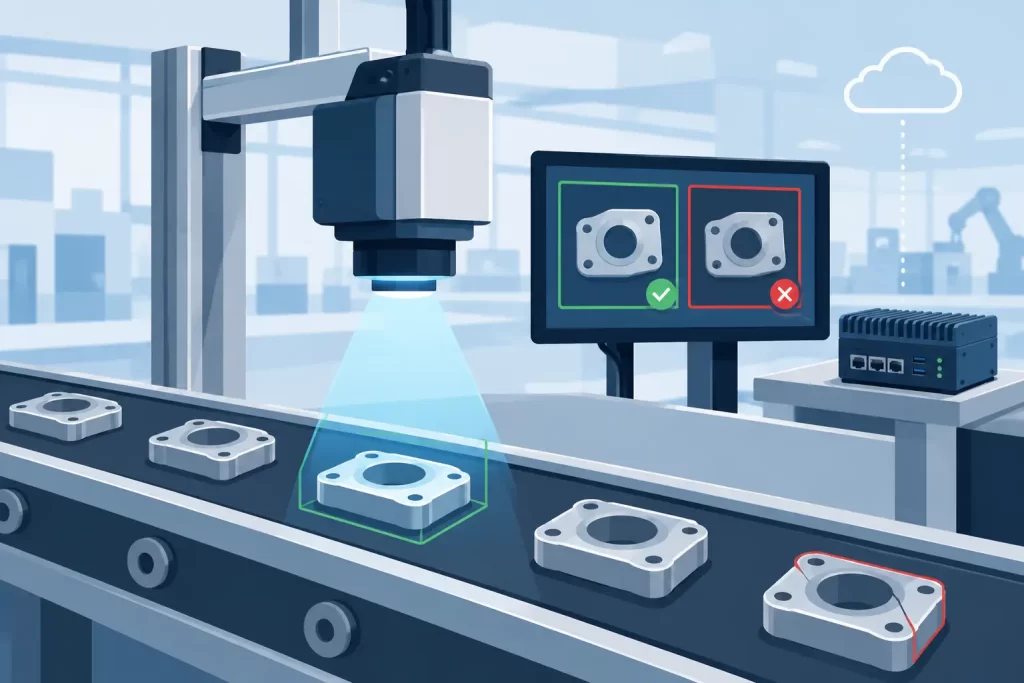
A faint scratch on coated metal, a pinhole in film, or an irregular bead on an extruded profile can become expensive only after it reaches the next operation. At line speed, human inspection is inconsistent, conventional vision rules are brittle, and delayed quality data leaves operators reacting to defects rather than controlling them. Automated surface inspection addresses this gap by converting image data into an immediate, repeatable decision at the point where the process can still be corrected.
For industrial teams, the objective is not simply to add a camera. It is to establish a reliable sensing and decision layer that distinguishes acceptable process variation from defects that require action. That distinction depends on the imaging system, the training method, the controller architecture, and the way results connect to the production line.
What automated surface inspection must detect
Surface defects rarely appear in one stable form. A scratch can vary in length, contrast, orientation, and depth. Contamination may be visible only under a particular lighting angle. Texture differences may be normal in one material batch and evidence of a process issue in another. A practical system must recognize the relevant pattern under real production conditions, not merely identify a defect in a controlled demonstration image.
Typical applications include inspection of painted and coated parts, rolled steel and aluminum, glass, films, textiles, wood panels, machined components, molded plastics, printed materials, and adhesive or sealant applications. The required decision may be pass/fail, defect type, defect location, severity category, or a count of defects per unit area.
The inspection target also determines the system design. A stationary component can be assessed with triggered image capture. A continuous web or moving strip may require line-scan imaging, encoder synchronization, and calculation of defect coordinates along the material. Highly reflective surfaces demand more attention to illumination than matte surfaces. There is no single camera configuration that fits every inspection task.
Inspection accuracy begins before AI training
Machine learning can classify complex visual patterns, but it cannot recover information that the camera never captured. Image quality is therefore an engineering requirement, not a secondary commissioning detail.
Lighting must create useful contrast between the expected surface and the defect class. Bright-field illumination can reveal print, color, or general appearance variations. Dark-field arrangements are often effective for scratches, raised edges, and particulate contamination because they emphasize scattered light. Backlighting can expose holes, edge defects, and dimensional variations. In demanding applications, multiple lighting geometries may be evaluated before selecting a model strategy.
Optics, working distance, depth of field, and motion control matter just as much. If the smallest critical defect is 0.2 mm, the pixel resolution at the inspected surface must support dependable separation of that feature from background texture and image noise. Motion blur, vibration, changing part position, and inconsistent exposure all reduce the usable signal.
This is where many projects make an avoidable mistake: they define accuracy only as a percentage from a sample dataset. A more useful specification includes defect size, allowed false rejects, missed-defect risk, line speed, repeatability, and the conditions under which performance must hold. A system that is accurate in a static test but fails when illumination ages or product finish changes is not production-ready.
Why edge processing changes the inspection architecture
In high-throughput manufacturing, transmitting every inspection image to a remote server can add network dependency, storage cost, and unpredictable response time. Some installations also have data-governance requirements that make off-site image processing impractical. Edge processing places recognition close to the camera, sensor, or machine controller.
For automated surface inspection, low latency supports immediate actions: reject a defective item, mark its position, stop a machine after a defined threshold, alert an operator, or adjust upstream process parameters. The decision can be synchronized with conveyor position or a programmable logic controller rather than waiting for a cloud response.
Edge architecture does not eliminate centralized systems. Recorded images, defect maps, production statistics, and model updates may still be sent to a plant server or quality database. The distinction is operational: the real-time decision remains available even when network bandwidth is limited or connectivity is interrupted.
NeuroTechnologijos applies this approach through trainable NT Adaptive controllers and server-side software modules that support recognition from images, video, vibration, audio, and other free-form signals. Hardware formats such as embedded boards, PCIe interfaces, and dedicated controller units allow the recognition layer to fit the available industrial computing architecture rather than forcing every application into a single platform.
Trainable recognition versus fixed vision rules
Traditional machine vision systems often rely on thresholds, edge measurements, template matching, and manually tuned filters. These methods remain effective when the object geometry is stable and the defect has a clear, repeatable appearance. They can be simple to validate and computationally efficient.
Their limitation appears when acceptable variation overlaps with defect appearance. Consider brushed metal, woven fabric, natural wood, or molded surfaces with changing texture. Rule-based logic may require repeated adjustment as material lots, finishes, or lighting conditions change. Adding more rules can increase maintenance effort without improving reliability.
A trainable recognition approach can learn categories from representative examples. Instead of defining every visual rule, engineers provide examples of acceptable surfaces and relevant defect classes. The controller then classifies new observations according to learned patterns. This is especially useful when defects are irregular, multi-scale, or difficult to describe mathematically.
Training data still requires discipline. Samples should represent normal production variation, not only ideal parts. Defect examples should cover realistic locations, orientations, and contrast levels. Borderline cases need an agreed quality disposition before they enter the dataset. If human inspectors do not consistently agree on whether a feature is a defect, the automated system cannot be expected to produce an unambiguous result without a clearer specification.
Designing an automated surface inspection cell
A successful deployment starts with the production decision, then works backward to the sensor and controller. The following elements should be defined during feasibility work:
- The smallest defect and surface condition that must be identified.
- The field of view, material speed, part spacing, and available inspection time.
- Lighting geometry, camera resolution, lens selection, and mechanical protection.
- The required machine response, including reject timing, alarms, traceability, and PLC signals.
- Data retention requirements for images, defect records, and production reports.
This information exposes trade-offs early. Higher resolution can reveal smaller features but may increase image volume and processing demand. Aggressive sensitivity can reduce missed defects but may increase false rejects. Multiple cameras can remove blind spots but introduce calibration and synchronization work. The correct balance depends on the cost of escape, the cost of rejecting good material, and the production process’s ability to respond to inspection data.
Environmental design is equally practical. Cameras and lighting need protection from dust, coolant, heat, washdown, and vibration. Industrial enclosures, stable mounting, controlled illumination, and cleaning access are often more valuable than adding algorithmic complexity after installation. A surface inspection system is a measurement system first, and it must remain stable over months of operation.
From defect detection to process control
The strongest business case for automated inspection is not a better defect image archive. It is faster process feedback. When defect type, location, and frequency are captured consistently, quality teams can correlate failures with tool wear, coating parameters, material batches, machine settings, or shifts.
For example, a localized recurring defect may indicate damage on a roller or forming tool. A gradual rise in surface contamination may point to cleaning degradation. A defect map across a continuous web can identify whether an issue repeats at a fixed machine interval. These patterns are difficult to establish from manual checks and sporadic samples.
Inspection results should therefore be structured for action. A reject signal handles the immediate unit-level decision, while defect classifications and timestamps support root-cause analysis. In some processes, the system can trigger inspection escalation or a controlled machine stop when defect rates exceed a defined threshold. Closed-loop adjustment is possible, but only after the relationship between the observed defect and the controllable process parameter has been validated.
Keeping performance stable after commissioning
Commissioning is the start of operational ownership, not the end of the project. Lighting output changes, lenses become contaminated, materials evolve, and new defect modes appear. A maintainable system includes reference samples, periodic verification, image review for uncertain classifications, and a controlled procedure for retraining when product conditions change.
Engineers should monitor more than pass/fail totals. Changes in confidence distribution, defect-class frequency, image brightness, and false-reject rates can reveal degradation before it becomes a production disruption. When recognition is deployed at the edge, these checks can support local, deterministic decisions while preserving the evidence needed for engineering review.
The useful test is straightforward: can the inspection system identify the defect soon enough, accurately enough, and consistently enough for the line to act? When the answer is designed into the optics, training data, edge controller, and machine interface from the beginning, surface quality becomes a measurable process signal rather than a late-stage surprise.
