

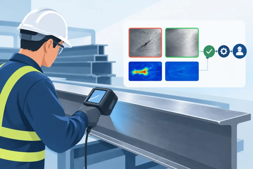
A surface inspection system earns its place on a steel line only when its output changes a production decision. Steel surface inspection results must tell an operator, PLC, or quality system what was found, where it occurred, how severe it is, and whether the material can continue, be downgraded, reworked, or rejected. A high defect count without location, confidence, and repeatability is not actionable quality data.
For steel producers, processors, and OEMs, the engineering challenge is not simply detecting visual variation. It is separating true defects from scale, oil, changing illumination, roll marks, water, vibration, and normal product texture at line speed. The useful result is therefore a controlled measurement output, not an image archive.
What Steel Surface Inspection Results Should Contain
The inspection result should begin with a defect classification, but classification alone is insufficient. A practical record connects the detected condition to coil, slab, plate, strip, or part identity and to its physical position. That makes it possible to correlate a defect cluster with a casting sequence, pickling stage, rolling stand, coating process, or handling operation.
A complete result typically includes defect type, severity or estimated dimensions, surface side, coordinate or length position, timestamp, production order, and model confidence. The exact fields depend on the process. On a continuous strip line, longitudinal and transverse position are central. For discrete fabricated parts, a camera-relative coordinate may be converted to a CAD feature, fixture location, or robot reference frame.
Severity thresholds require deliberate definition. A small scratch may be acceptable for structural stock yet disqualifying for exposed automotive panel or appliance-grade material. The inspection system should preserve the measured evidence while allowing acceptance rules to vary by product grade, customer specification, and downstream process route.
Detection Is Not the Same as Disposition
A vision model may identify a dark linear feature, but the production system still needs to determine whether it is a scratch, a crack, a roll mark, residual scale, or harmless texture. It may also need to decide whether the feature exceeds the permitted length, width, density, or zone-specific limit.
This distinction matters because false rejects carry direct costs: unnecessary downgrades, reinspection labor, and disruption of material flow. Missed defects create a different and often more serious cost through claims, rework, safety exposure, or field failure. The correct operating point depends on the quality risk of the application, not on a generic target for model accuracy.
Why Results Drift on Real Steel Lines
Steel is a difficult visual target because its appearance is process-dependent. Hot material may produce scale and thermal shimmer. Cold-rolled, galvanized, painted, or polished products create distinct reflectance behavior. Surface contamination, camera window deposits, and changes in illumination angle can alter image contrast without any underlying change in product quality.
A model trained only on clean sample images will often perform well in a demonstration and poorly after weeks on the line. Inspection results must be evaluated across the operating envelope: product grades, widths, speeds, surface finishes, temperatures, lighting states, and expected contamination levels. The relevant question is not whether the system recognizes a defect in isolation. It is whether it maintains defined detection performance when the line behaves normally.
Mechanical factors are equally significant. Camera vibration, encoder slip, inconsistent standoff distance, lens focus shift, and synchronization errors can degrade positional accuracy. If a line stops and restarts, the system must preserve material tracking so that defect coordinates remain meaningful. An image with no reliable relationship to the product is evidence that cannot be acted on efficiently.
Calibration Must Be Treated as Production Control
Calibration is often reduced to an installation task. In operation, it should be managed like any other controlled measurement process. Optical calibration verifies field of view, scale, focus, exposure, and illumination uniformity. Geometric calibration aligns multiple cameras and links image coordinates to line coordinates. Process calibration verifies that reported defect sizes and locations agree with validated physical measurements.
Reference samples are useful, but they should reflect actual failure modes rather than idealized marks. A controlled set might include scratches, pits, inclusions, cracks, coating defects, scale patterns, and acceptable surface variation. Repeated checks against these samples reveal whether performance is shifting before a quality escape occurs.
Building a Result Pipeline for Fast Decisions
The architecture should move from acquisition to action with minimal ambiguity. Cameras or line-scan sensors acquire material data; preprocessing normalizes usable signal characteristics; a trained classifier identifies patterns; rules combine classification with product requirements; and the result is passed to operator displays, PLC logic, manufacturing execution systems, or quality databases.
Edge processing is particularly relevant where line speed, image volume, latency, or network constraints make centralized analysis impractical. Sending all raw video to remote infrastructure can introduce bandwidth and retention burdens while delaying reject or diversion decisions. A local controller can classify the signal close to the machine and transmit compact, structured events rather than an unfiltered stream.
For applications requiring rapid pattern recognition with constrained power and embedded deployment, trainable neural hardware can provide a practical alternative to large server-only inference stacks. NeuroTechnologijos applies this approach through NT Adaptive controllers and software modules designed to process image, video, vibration, audio, and other free-form signals in industrial environments.
The trade-off is that edge deployment does not remove the need for engineering discipline. Models still require representative training data, version control, validation, and controlled updates. The advantage is that decision latency and system dependence are easier to manage at the point of inspection.
Train for the Production Variability That Matters
A useful training dataset includes both defects and acceptable conditions that could be mistaken for defects. On steel surfaces, the negative class is not simply a blank image. It contains normal grain, weld seams where applicable, scale, oil film, stamped features, coating variation, illumination gradients, and expected marks from the process.
Defect examples should be labeled to the precision required by the decision. If the system only needs to trigger manual review, broad categories may be sufficient. If it controls automatic sorting or customer-grade disposition, labels must distinguish defect subtype, size, zone, and severity with much greater care.
Model performance should be reported using production-relevant measures. Precision and recall are useful, but they should be broken down by defect type, product family, line speed, and surface condition. A single aggregate score can conceal poor performance on a rare but critical crack class. Confusion matrices, false-reject rates, missed-defect rates, and decision latency provide a more useful operational view.
Present Results for Operators and Quality Engineers
An operator screen should not force a user to interpret every image. It should present the current material state, defect map, severity, confidence, and required action clearly enough to support a timely response. The associated image crop or video segment should remain available for verification, especially while the system is being tuned.
Quality engineers need a different view. They require trend data by coil, heat, shift, product grade, machine state, and defect location. A recurring pattern near one strip edge may point to a roll condition or guide alignment issue. A rising density of coating defects after a process adjustment can reveal a cause before finished inventory accumulates.
Traceability turns inspection from sorting into process learning. When surface events are connected to upstream parameters and downstream quality outcomes, teams can distinguish a sensor artifact from a real process change. That is where inspection data begins to support root-cause analysis rather than merely documenting nonconformance.
Validate Results Before Automating the Consequence
Automatic rejection should be introduced in stages. Begin with shadow-mode operation, where the system records recommendations while experienced inspectors continue their normal decisions. Compare outcomes over enough product and process variation to expose edge cases. Then automate lower-risk actions, such as flagging, marking, or routing to review, before enabling irreversible material disposition.
Acceptance criteria should specify more than recognition accuracy. Define maximum allowed response time, coordinate error, missed-defect rate for critical classes, false-reject rate, availability, image retention rules, and behavior when confidence is low. A well-designed system should have a defined fallback state rather than silently converting uncertainty into an accept decision.
The most valuable steel surface inspection results are those that arrive early enough, with enough context, to change the next physical action. Design the measurement, classification, and data path around that decision, and the inspection station becomes part of process control rather than a final checkpoint.
